Model |
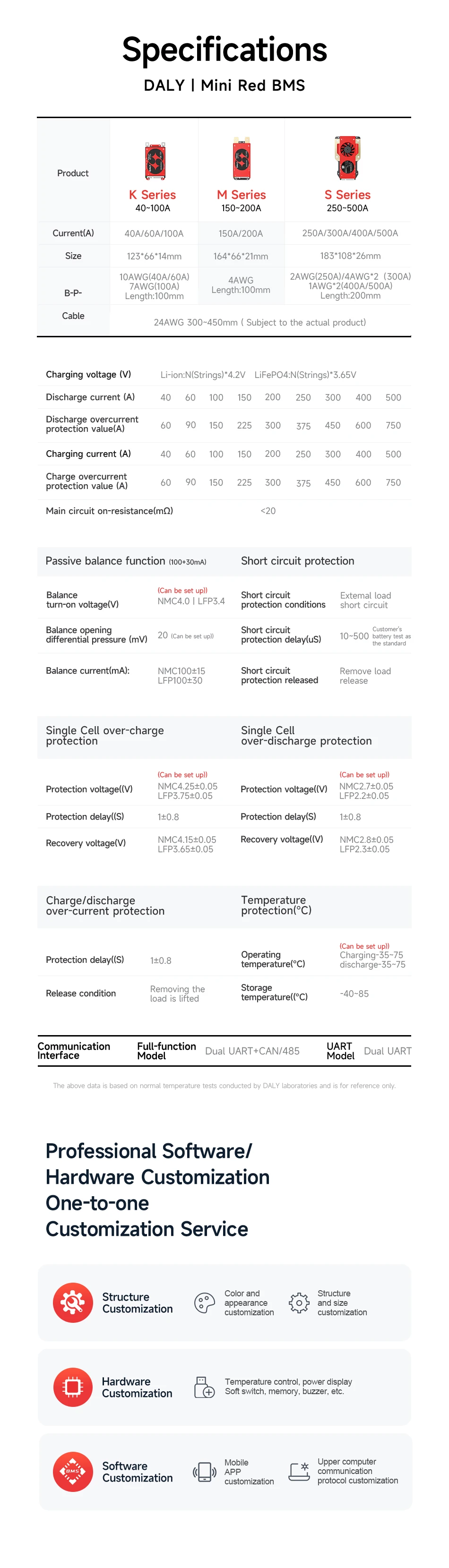
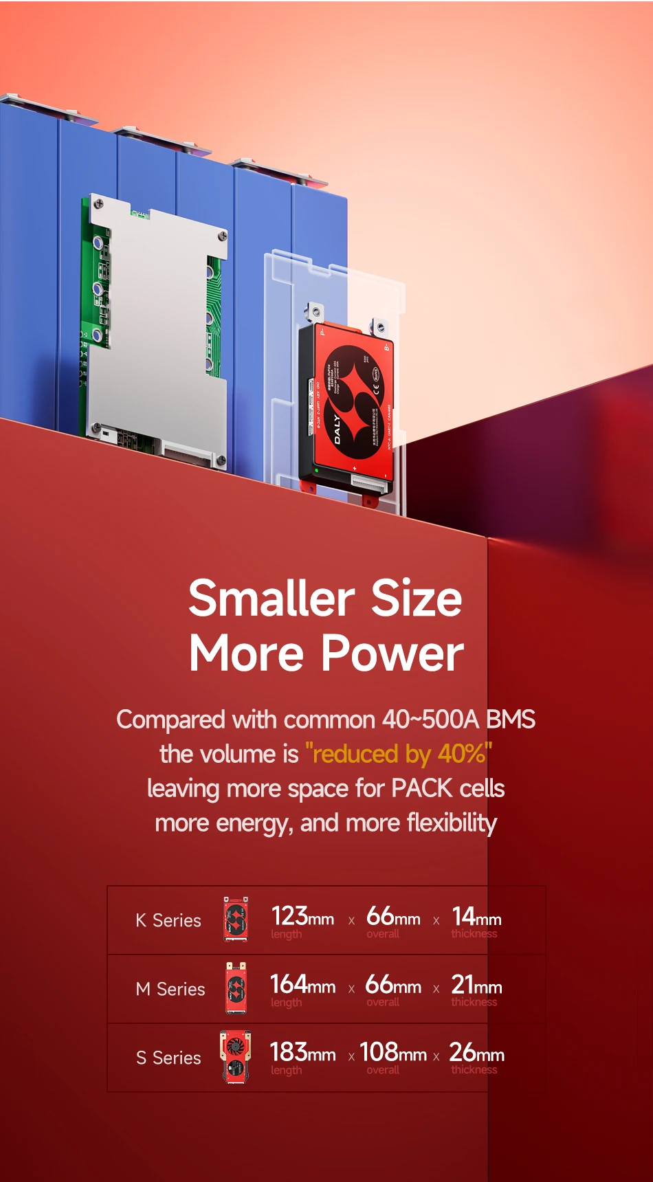
DALY SMART Balance BMS: RTK(40A-100A) RM(150A-200A) RS(250A-500A) |
Battery Type: Lifepo4(3.2v) /Li-ion(3.7v) |
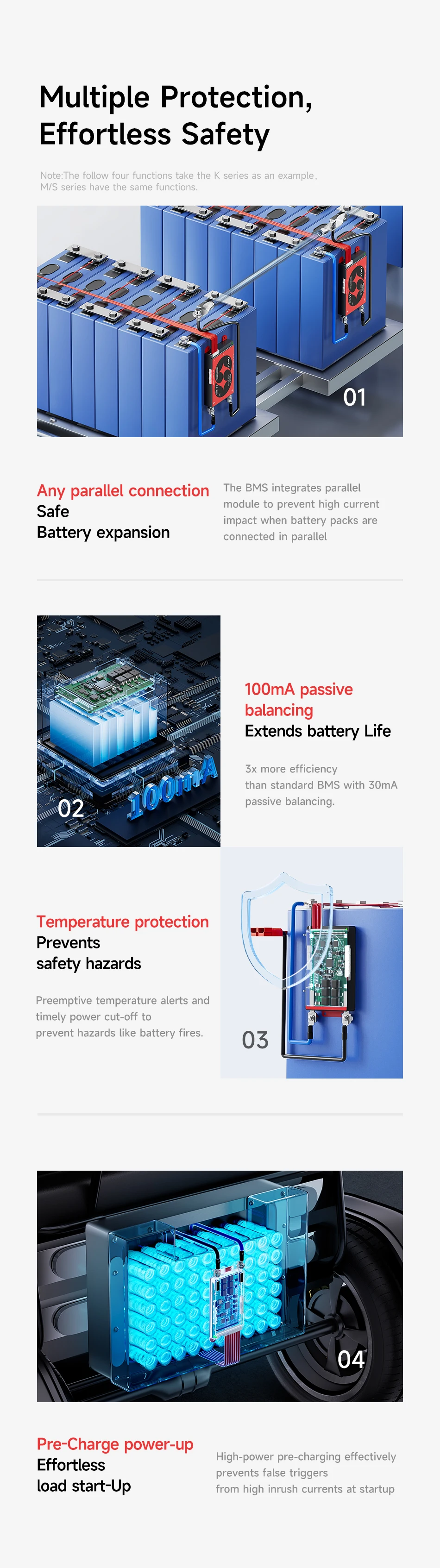
Balanced method: Passive Balancing 100mA |
Optional strings range:4S 6S 7S 8S 10S 12S 13S 14S 16S 20S 24S |
Optional current range:40A-500A |
Parallel current limiting: 1A (BMS can be used in parallel directly.) |
Accessories: Bluetooth module |
|
Usage Scenario |
Used in RV energy storage,photovoltaic energy storage,home and outdoor energy storage,
electric vehicles,tricycles,forklifts,tourist vehicles,golf cart etc. |
|
How to choose the right BMS |
Attention |
Illustration |
Mismatched BMS Consequences |
|
|
Lithium |
BMS type and lithium battery type must be in |
1、BMS damaged,even bms and battery burn out |
battery type |
one-to-one correspondence(Li-ion/Lifepo4) |
2、The battery cannot be fully charged and discharged |
|
|
|
Number of battery pack |
BMS strings and battery strings must be in |
BMS and battery burn out |
strings |
one-to-one correspondence |
|
|
Selection method |
load maximum power÷(string number of battery×overdischarge voltage)×coefficient |
in experience |
Depending on the battery usage scenario, the coefficient value is also different |
|
Please consult customer service for specific values |
|
Specialty |
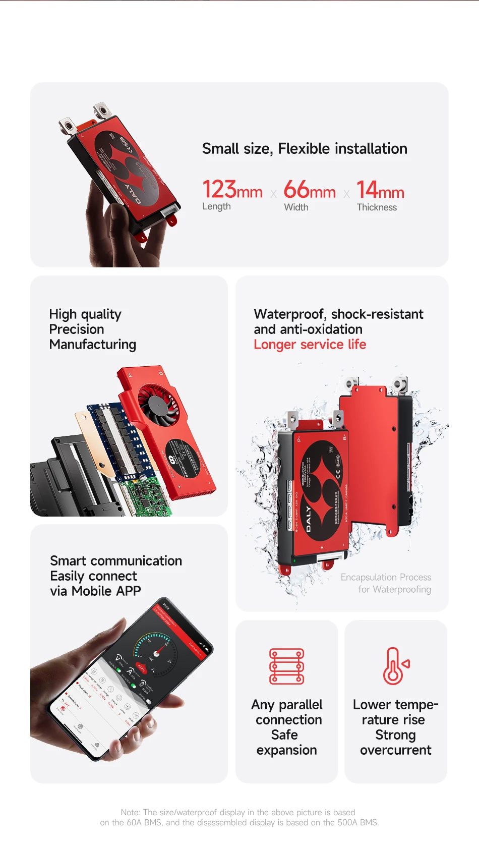
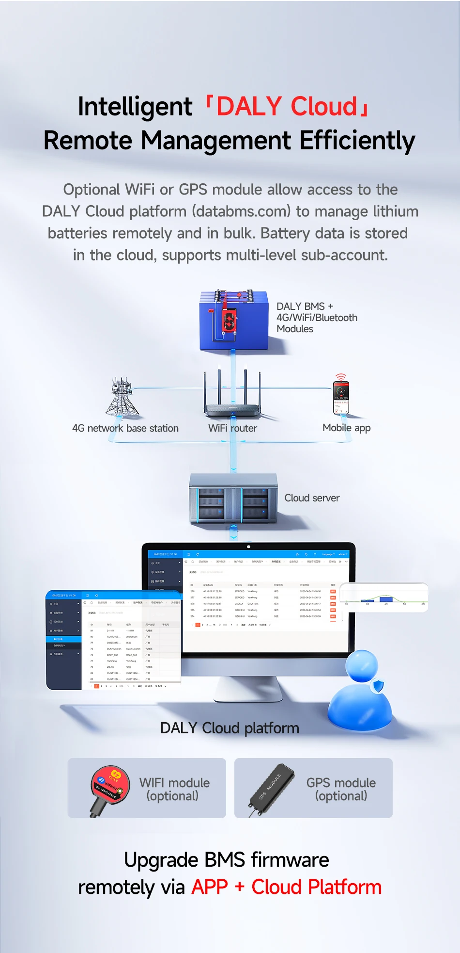
Bluetooth function:Monitoring battery data in real time by connecting to the APP |
|
Superiority |
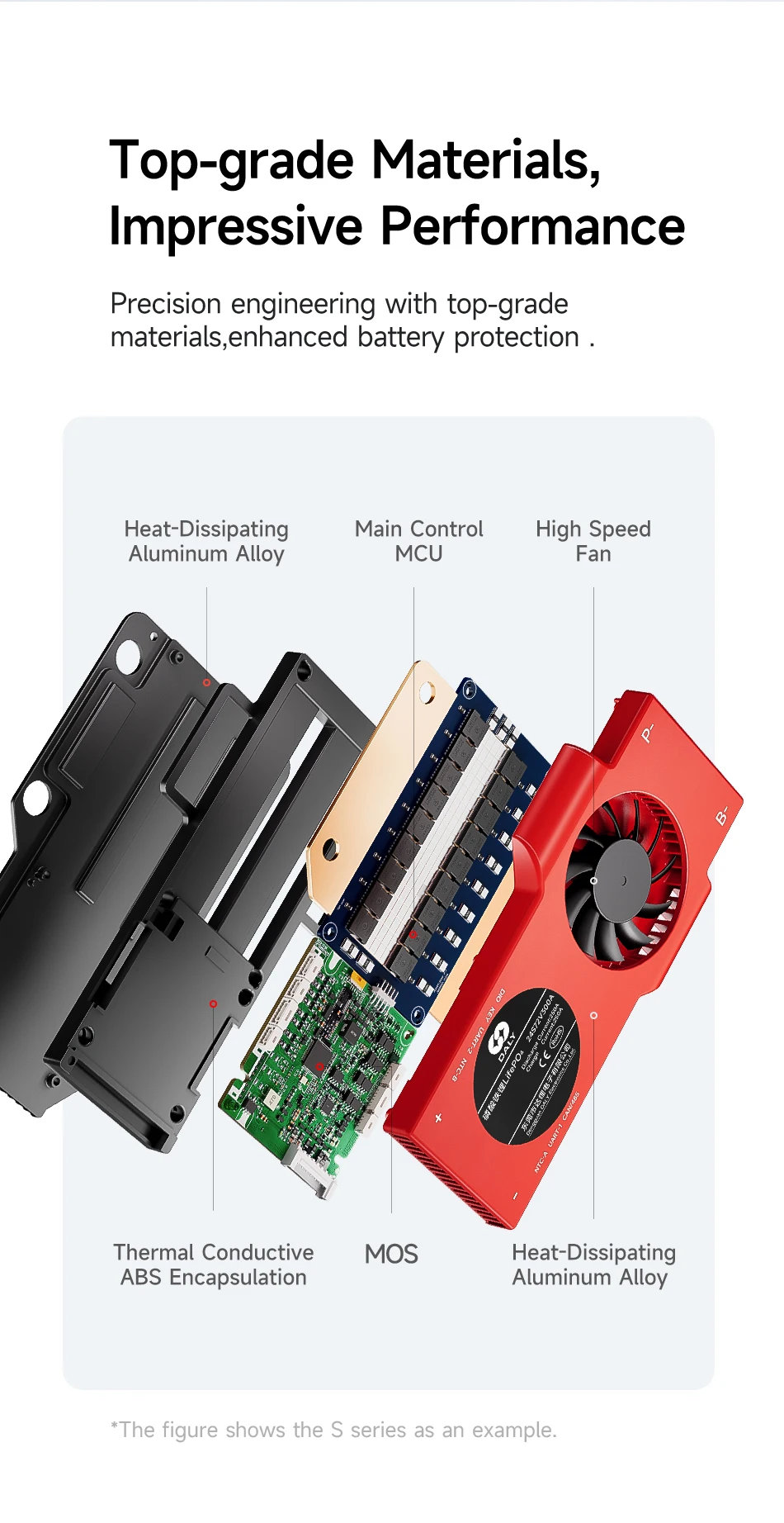
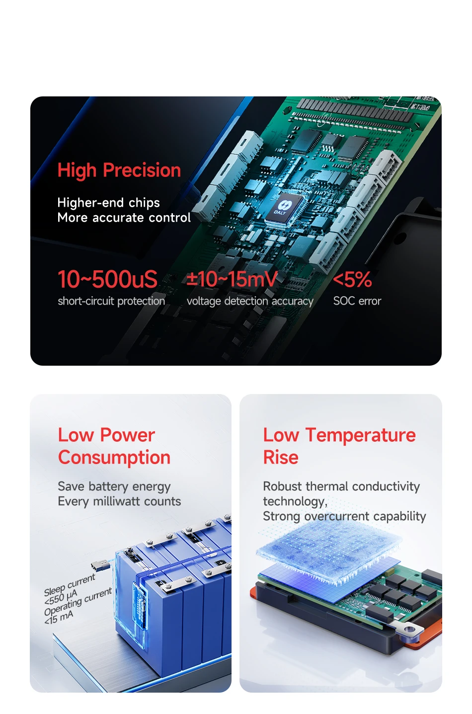
1、High-quality microelectronic components:precise and fast IC.Low resistance,high withstand voltage MOSFET. |
2、Through the Bluetooth APP, the battery data is constantly monitored. |
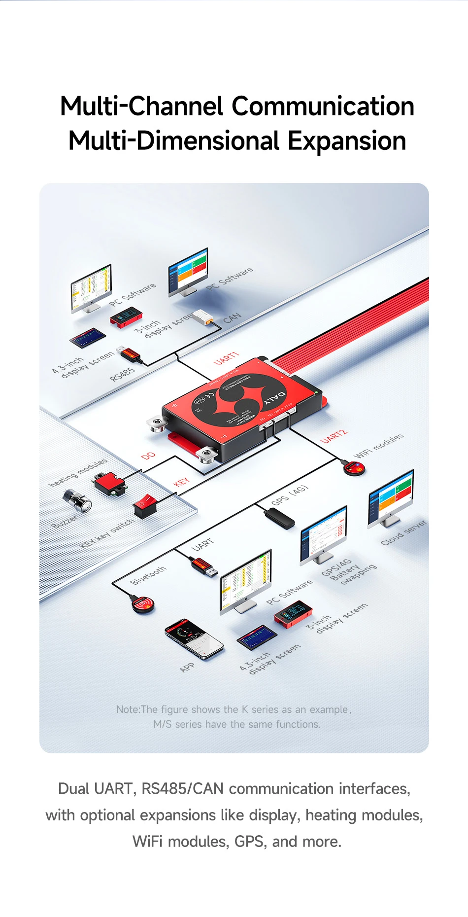
3、A variety of accessories,can easily control the data and modify the parameters. |
4、A variety of communication modes,data monitoring,alarm backtracking,data reading, and upgrade can be easily realized |
5、Thermal silica,accelerate the heat dissipation.Ensure the smooth operation of the battery. |
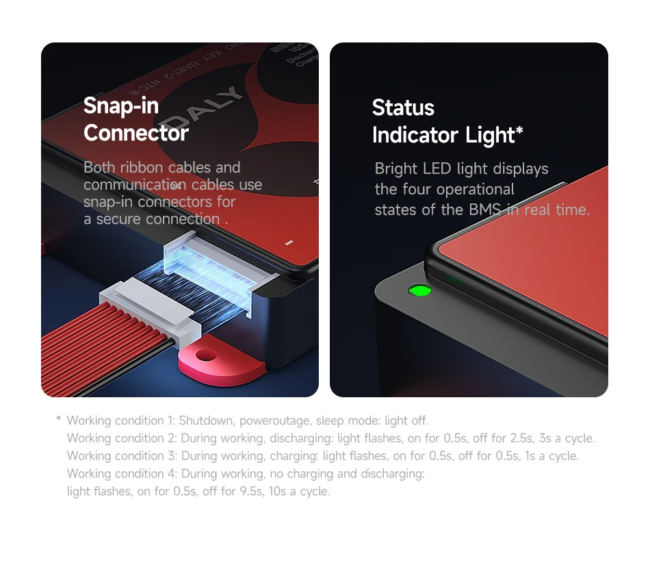
6、Preset interface,buckle cable,make the connection more convenient. |
|
Basic Functions |
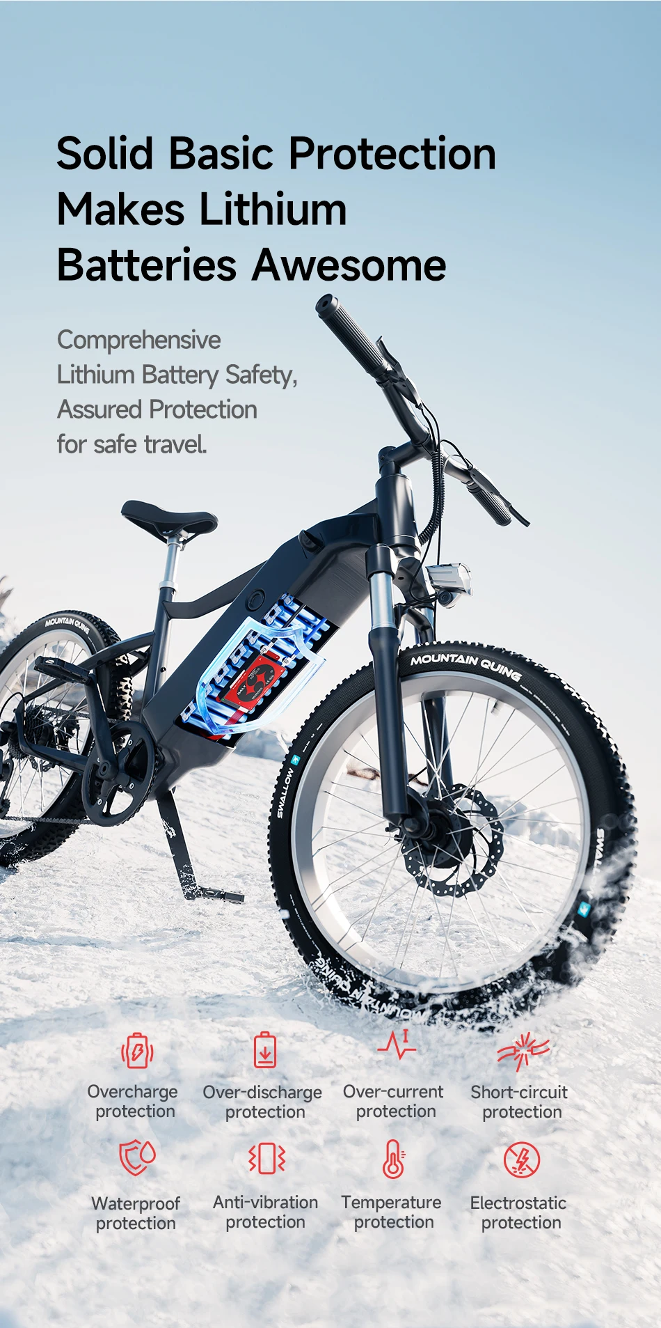
Over-charging protection |
Over-discharging protection |
Over-current protection |
Temperature protection |
Disconnect protection |
Short Circuit Protection |
Balance Function |
Short Circuit protection recover |
|
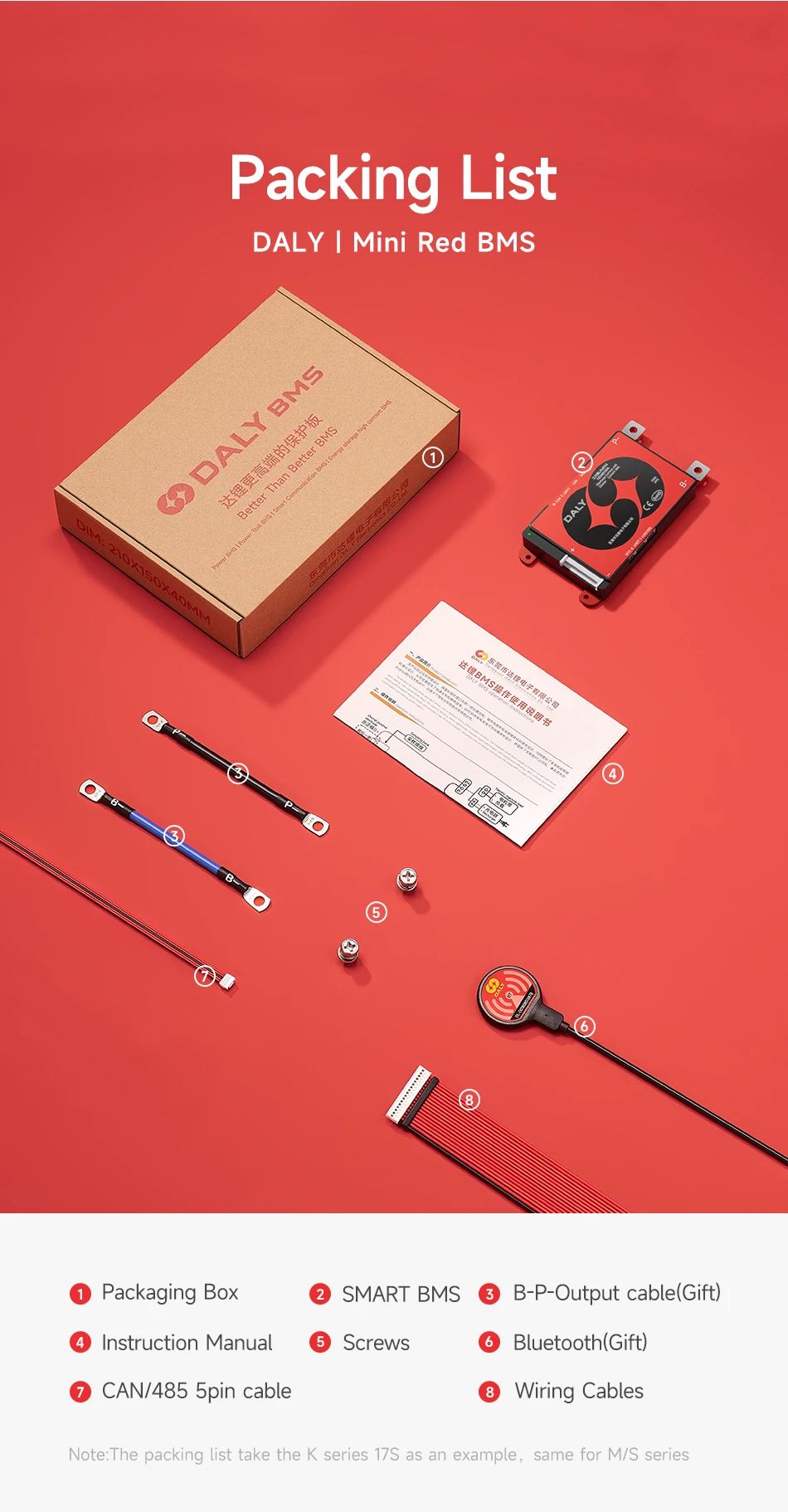
Package Contains |
BMS*1pcs |
Sampling cable*1pcs |
Temperature probe(NTC)*1pcs |
Bluetooth module *1pcs |
English manual *1pcs |
|
|
Communication function |
UART/RS485/CAN |
|
Balance cable connection |
Preparation |
Find the total positive and total negative of the battery pack. |
Find B-/P- of BMS |
Insert temperature probe (NTC) into the BMS |
Welding |
Note: When soldering, the balance cable cannot be inserted into the BMS |
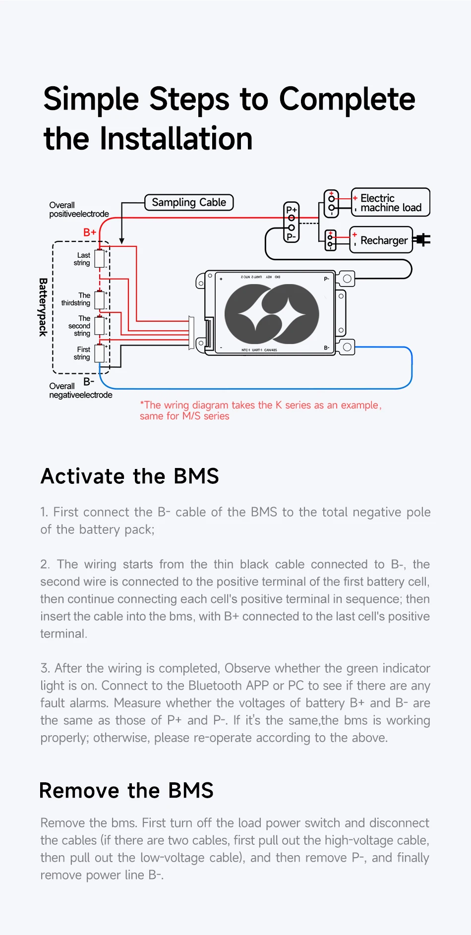
(1)Weld Sampling cables: Start from thin black wire to B- (total negative),then connect each cell's positive in order. Last red wire to B+ (total positive)
*Note: Do NOT plug into BMS during welding. Insulate unused wires. |
(2)Check voltages: Use multimeter or wire tester to confirm each cell'svoltage is normal. Fix any miswiring or poor soldering. |
(3) Weld output wires: Secure B- and P- to BMS with 10N·m torque; weld B-to battery negative.
*Note: Insulate P- before final connection. |
(4) Plug NTC and Sampling cable: Insert NTC, then plug sampling cable toauto-activate BMS. |
|
Voltage measurement |
measure whether the battery voltage(B+→B-)is consistent with the output voltage of the BMS(B+→P-). |
If the two voltage values are equal, it means that the BMS is working normally. |
|
|
Passive Balance |
Balanced Start Voltage: |
3.4V |
Balance off voltage |
3.6V |
Balanced Opening Voltage Difference: |
≥20mV |
Balance Current: |
100±30mV |
Balanced start when both of the following conditions are met: |
1.The maximum voltage difference between individual cells is ≥ the equalization opening voltage difference |
2.The voltage of each individual cell>The balance turn-on voltage |
3.The voltage of each individual cell<The balance off voltage |
Note:When the battery is at low voltage and discharged, the maximum balance
current is 0.8±0.2A |
|
How to wake up BMS |
If any of the following conditions are met, the system exits the sleep mode
and enters the normal running mode: |
1.Plug in charger/load. |
2.Press the button and release the button |
3.With 485, CAN communication activation. |
Note: After the single or overall over-discharge protection, it enters sleep mode, wakes up periodically every 4 hours, and starts charging and discharging MOS. If it can be charged, it will exit the resting state and enter normal charging |